Thursday, 31 March 2011

Error Checking

The importance of error checking is that if even one digit of binary is changed a whole file could cease to make sense.
Right so what ways can we use to check:


Single Parity - Odd
In the example of ASCII which we used in an earlier post we can can check for errors using the 8th digit.
This works by changing the 8th digit to make all the 1's = an odd number
so when we look back at all the strings in the object we are checking we can see if all the bytes = odd numbers, if not then we know that a bit has been changed.


in the same way we can use the even system which also uses the same system but you change the 8th digits to make the bytes = even numbers.


Right so can use this to detect errors but now to correct them:
we can use the Majority Vote System this involves sending data three times. We can then take the most common digit for each bit recieved to find out the correct data.
e.g. we try to transmit: 01100110
So we get back:


01100110
01000110
01101010
in red we can see the errors (least common digits)
we can then use the common digits to repair the data.


The only disadvantage of this is that we have to send data three times...


Hamming Distance


This is the distance required to change one string into another. thus finding the distance between the two stings.


e.g. 1110 isn't the same as 1111
to change 1110 to 1111 you need to change the least significant figure to 1


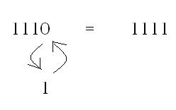
1 move required (1 digit needed changing)
the hamming distance between:
1011101 and 1001001 is 2

These can be represented as images too!
This being an example of a 3 bit cube


This is a hypercube for  4 bits. you can find the distance using these diagrams by taking the shortest route from one set of bits to another for each black circle you go past that is 1 extra to the distance.

Gray Code aka "Reflected Binary Code":

if one switch has 2 states: on and off
and these are coded as 011 and 100
using hammings distance we know that there is a distance of 3 so between the states 011 and 100 we have: 001 and 101
(This would look like this:  011 — 001 — 101 — 100)

This means we cannot tell if the "real" posistion is 011,001, 101 or even 100.
"The reflected binary code solves this problem by changing  only one switch at a time, so there is never any ambiguity  of position"

                    Dec Gray   Binary
                    0   000    000
                    1   001    001
                    2   011    010
                    3   010    011
                    4   110    100
                    5   111    101
                    6   101    110
                    7   100    111

The gray system means that the position change to get to the next code (hammings distance) is only 1, Meaning that there are no "transision" codes between when a switch is changed.
This means grays code goes up in hammings distance of 1 instead of using natural binary:
64 32 16 8 4 2 1


Information Coding Schemes

ASCII - American Standard Code for Information Interchange

This is a way in which we can represent characters.
There are 127 different characters using the stardard (non-extended) ascii table:


As you can see the table doesn't show binary this is because it would require too much space on the table, but, we can convert the dec number to binary very easily.
This means that it would use 7 digits to represent it right?
Nope, ASCII actualy uses a byte, this is because we can use the last digit to add extended ascii (extra characters). Also we can use the 8th digit as an error checking method (we will talk about this in another post).

Unicode
Not much to say about this but basicly:
  • It uses 16 bits which is a huge amount. So huge that we can use it to represent all languages and mathematical symbols.
  • And they would normaly use hex.


Wednesday, 9 March 2011

Systems Life cycles

Following  structured lifecycle can reduce the risk of projects failing. When projects fail....at best the is a lot of money, at worst people loose their lives.

There are 5 phases of the lifecycle;

Analysis
Why???
- New business opportunities
- New laws
- Mergers
- New technology etc.

Design
The design phase is used to create a specification for a system that will meet the need identified in the analysis

Included is;
- Hardware
- Software
- Data
- Buildings?
implementation
- Build the system
- Hardware racking
- Software install
- Data migration
- Training
- Documentation

Testing
- Verify (have we built the thing right)
- Test part on their own
- Test the whole
- Test the people

Evaluation

Used for:
- Validate (have we built the right thing)
- Check it's effectiveness
- Identify future work

After
Maintenance, where we;
- Fix/detect problems
- Adapt the system over time
- Add new features
- Which can cause the whole cycle to be used again for big changes.

Tuesday, 8 March 2011

Finite State Machines

A Finite State Machine:
  • This is a machine that consists of a fixed set of states.
  • Has a set of allowable inputs
  • Has a set of possible outputs the are dependant upon the current state
  • A FSM that has no outputs is a finite state automation
We can represent a FSM with finite state diagrams or state transistion tables.

A simple FSM would be a door. We can use:


To represent a state. you would put an arrow pointing to this if it was the starting state, or a smaller circle within it if it was the closed state(known as the accept state).


To represent a connector which shows the transistion between states.
You would write the transistion (input and output) on the connector.

So a basic door would have two states: Opened and Closed
and the inputs would be opening and closing              
So:
We can replace longer state names with: S1, S2, S3...  and then add a key to show what they are.
Also with some FSM we can add an output to each connector (this would go next to the input separated by a comma.

Decision Tables
This can be re written as pseudo
If X is greater than 6 AND Y is less than 7 OR Z is  equal to 3
Then  Output “Pass”
Else Output “Fail”


Sunday, 6 March 2011

Representing Sound

Analogue: This can be any value (it is continuous)
Digital: This has only certain values (discrete values)

Signal: This is the electrical version of data, propagated in a non-electrical way (physical e.g. water or air)
We use a transducer to convert between electrical and non-electrical. (e.g. a microphone).
Getting the sound wave into an analogue electrical signal is a start – but computers can only work on digital signals.
...ADC!
Step 1: The continuous (analogue) sound signal is sampled at regular intervals. This is called Pulse Amplitude Modulation (PAM)
Step2: Each value is then rounded down to an approximate value dawn from a range of possible discrete (digital) values.
Step3: The value is then stored as a binary digit
Step4: The technical term for approximating a sound sample to the closest digital value is quantisation
            Each quantised number represents a Pulse Code Modulation (PCM)
            Each individual PCM (binary number representing one sample from the sound) is stored in sequence        in a file to record the sound in a digital, binary file

Because of this quantisation causes there to be lose in data as it is rounded to the nearest figure. This means quality will be lost. 
... Nyquist's theorem :D
Nyquist’s theorem states that: “We must sample at a frequency at least twice the rate of the highest frequency in the signal”

Common file formats for sound:
•WAV: 1min = 2.5Mb
•MPEG (used in .mp2, .mp3, .mp4) removes any frequencies the ear/brain cannot deal with.
•Which makes the file about 10% of the original. 1 min = 0.25Mb

Synthesisers: These use MIDI (Music Information Digital Interface) 
These don't save the data for the sound, it actually stores the notes used, which instruments and duration etc. for which can be played differently on a synthesiser by changing small parts of information e.g. which instrument it's played on.

Streaming Music:
•The server sends the sounds bit by bit
•The client buffers it and plays it when it has enough to keep going whilst buffering more
Advantages include:
•No need to download the file – just start playing as you buffer
•No need to save any files
•Digital Rights Management (DRM) - Can't be easily copied without recording manuely
Disadvantages include:
•Not being able to access these without being c
•Internet lag can cause music to cut off.

Tuesday, 15 February 2011

Bitmaps, Vectors and Compression Techniques

Bitmaps
These are mapped array of bits. The array is made up by 1's and 0's which when arranged create a shape like so:

for more colours more bits per colour would have to be assigned to each pixel.
A pixel being the smallest addressable point of an image.

Problems with bitmaps: Bitmaps take up alot of space to store e.g.
A true colour (24 bit) bitmap taken on a 7MP camera: 
7MP = 7,000,000 pixels
Using 24 bits per pixel = 168,000,000 bits
=  21,000,000 Bytes
= 21,000 KB
= 21MB!
Vectors
Vectors unlike bitmaps don't store a picture as mapped arrays. Vectors use geometric information and properties) needed to recreate an image.
e.g.

Bitmap file
1111111111111111111111111111111111111111…….7 million times = 20MB!
Vector file
Rect(0,0, 2700, 2700, black, filled, none)
= just a few bytes!


The advantage of using vectors information on how to make the picture (not the actual picture itself is that firstly it takes less space to store (quicker to load too!), and that we can scale these images well without it sstarting to pixelize like a bitmap. This is because to make a larger image with a vector the property given for the size to the computer would just need to be increased and it could recreate the image, but with a bitmap it would have to assign more pixels which need more colours(which colours). These colours would need to be interpolated(higher form of averaging).
The only disadvatage of using a vector is that for the computer to create instruction to make an image it has to see you make it (you would a specific type of program to create a vector).


Compression Techniques
we have 2 options for compressing an image.
1) lossless compressing. This is compressing the image without lossing any information:
 Run Length Encoding (RLE) replaces continuous blocks with just the colour and the number of blocks

2)Lossy compressing. This is a form of compression that losses information.
Remove bits we find hard to see/won’t notice (JPEG) - Every time you save a JPEG again as a JPEG you lose more information!


Tuesday, 7 December 2010

Machine Level Architecture

What are the basic internal components of a computer system?
The  basic internal components of a computer system is the: Proccessor, Main memory, the I/O and the bus which connects them together. This is known as the CPU (Central proccessing unit).

3-Box model:

Proccessor
The proccessor is the component which runs programs and looks after other components

Main memory
This is also known as the immidiate access store (IAS). this components is used to store instructions and data. This is made up of RAM and ROM.

RAM (Random Access Memory): This only holds quick access data/instruction, and only when the computer is turned on.

ROM (Read-only Memory: This is used to store programs needed to start the computer (bootstraping)

I/O
Everything that isn't in the CPU is a peripheral.

I/O controller: allows the computer to communicate with peripherals without the CPU knowing how they work.

I/O Ports: its a method of performing inputs and outputs between CPU and peripheral devices in a computer.

Bus
aka system bus or external bus. It connects the other components and is made up of several parallel wires.
There are 3 bus' the:

Address bus
A single direction bus that sends address' to the components of the three box model.
Data bus
This carries control signals between the 3-Box model.

Control bus
This carries commands from the CPU and sends back status from the other devices.